Deploy Site in AWS (ClickOps)
Objective
Important: This is a legacy workflow for deploying Customer Edge (CE) sites and is not recommended to use. A new workflow for deploying Customer Edge (CE) sites has been introduced and is now Generally Available (GA). F5 recommends you use the new Secure Mesh Site (v2) workflow for all your Customer Edge deployments. You can find this workflow here.
This guide provides instructions on how to create a CE Site using the Amazon Web Services (AWS) Management Console and deploy to an AWS virtual private cloud (VPC).
The procedural steps show you how to create a single-node mesh site with dual interfaces (ingress/egress gateway). However, this guide also incorporates the differences so that you can successfully deploy an AWS CE Site using both Mesh or App Stack and in any supported combination of nodes and interfaces.
Site Types and Scenarios
The scenarios in the table below have been successfully tested. The Network Address Translation Gateway (NAT GW) device in the table references the AWS NAT Gateway. However, technically, this should also work with third-party firewalls.
Note: In the Number of Nodes column, 1/3 indicates 1 or 3 nodes. IGW references Internet Gateway.
| Provider | Site Type | Number of Nodes | Gateway Type | Interfaces | Scenario |
|---|---|---|---|---|---|
| AWS | Mesh | 1/3 | Ingress/Egress | 2 | Behind IGW |
| AWS | Mesh | 1/3 | Ingress | 1 | Behind IGW |
| AWS | App Stack | 1/3 | - | 1 | Behind IGW |
| AWS | Mesh | 1/3 | Ingress/Egress | 2 | Behind NAT GW |
| AWS | Mesh | 1/3 | Ingress | 1 | Behind NAT GW |
| AWS | App Stack | 1/3 | - | 1 | Behind NAT GW |
Prerequisites
The following prerequisites apply:
-
A Distributed Cloud Services Account. If you do not have an account, see Getting Started with Console.
-
An account with AWS. See the AWS VPC Policies and Permissions Reference guide for permissions needed to deploy site. To create a cloud credentials object, see Cloud Credentials.
-
Resources required per node: Minimum 8 vCPUs, 32 GB RAM, and 80 GB disk storage. However, to deploy an F5® Distributed Cloud App Stack Site, 100 GB is the recommended minimum amount of storage. For a full listing of the resources required, see the Customer Edge Site Sizing Reference guide. All the nodes in a given CE Site should have the same resources regarding the compute, memory, and disk storage. When deploying in cloud environments, these nodes should use the same instance flavor.
-
Allow traffic from and to the Distributed Cloud public IP addresses to your network and allowlist related domain names. See F5 Customer Edge IP Address and Domain Reference for Firewall or Proxy Settings guide for the list of IP addresses and domain names.
-
F5 assumes that the VPC exists with a minimum of two subnets: one for the Site Local Outside (SLO) and one for the Site Local Inside (SLI). The CE generally references the SLO interface as eth0 and the SLI interface as eth1. It is also important to understand that both subnets have to be in a common Availability Zone, so the CE has one interface in the SLO subnet and another in the SLI subnet. For a single-NIC deployment (ingress gateway or App Stack), only a single subnet (SLO) is required.
-
Internet Control Message Protocol (ICMP) needs to be opened between the CE nodes on the Site Local Outside (SLO) interfaces. This is needed to ensure intra-cluster communication checks.
Important: After you deploy the CE Site, the IP address for the SLO interface cannot be changed. Also, the MAC address cannot be changed.
Procedure
This procedure provides instructions for creating a Secure Mesh Site with two interfaces (ingress/egress). Most of the objects and configurations are the same for single-node and multi-node sites. The steps differ only for the node instance and elastic IP address creation, where you must repeat the steps for each node in a multi-node site.
Create IAM Policy and Role
You must create an Identity and Access Management (IAM) role that is attached to the CE site, with minimal permissions configured for that role using an IAM policy. Therefore, you first create an IAM policy with the required permissions, and then create an IAM role that references that IAM policy.
Step 1: Navigate to policy creation page.
-
In AWS Management Console, navigate to the IAM service.
-
Under Access management, click Policies and then click Create policy.
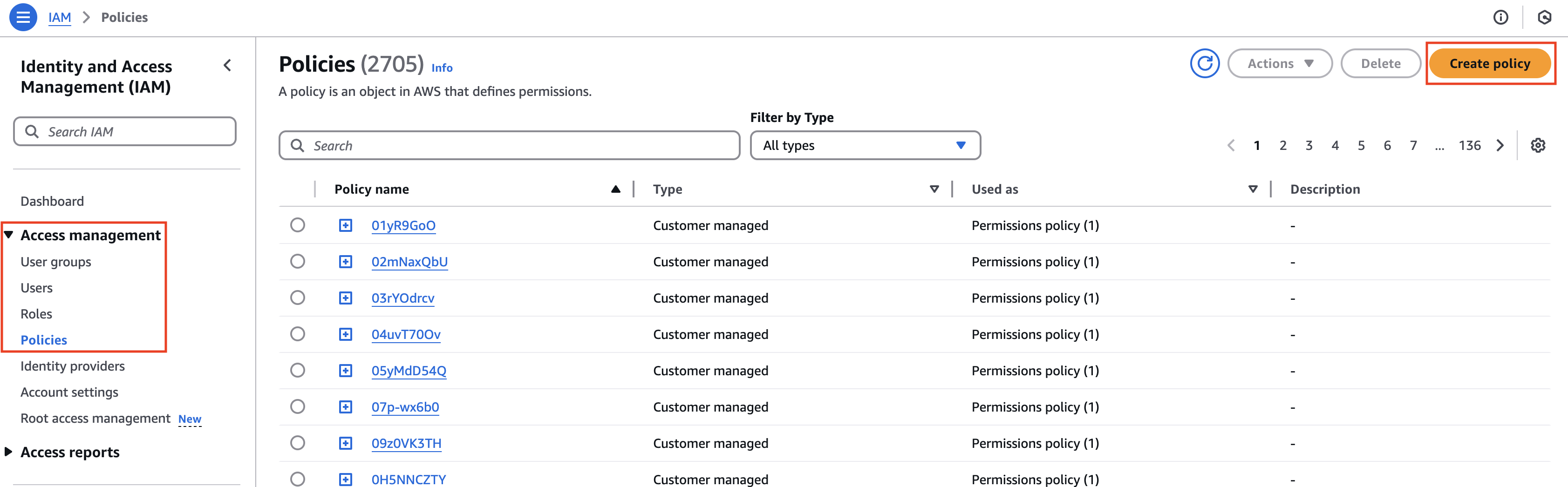
Figure: Create Policy
Step 2: Create and configure IAM policy.
-
From the Service menu, select EC2.
-
In the Filter Actions box, search for and select the DescribeInstances, DescribeTags, and autoscaling:DescribeAutoScalingInstances permissions.
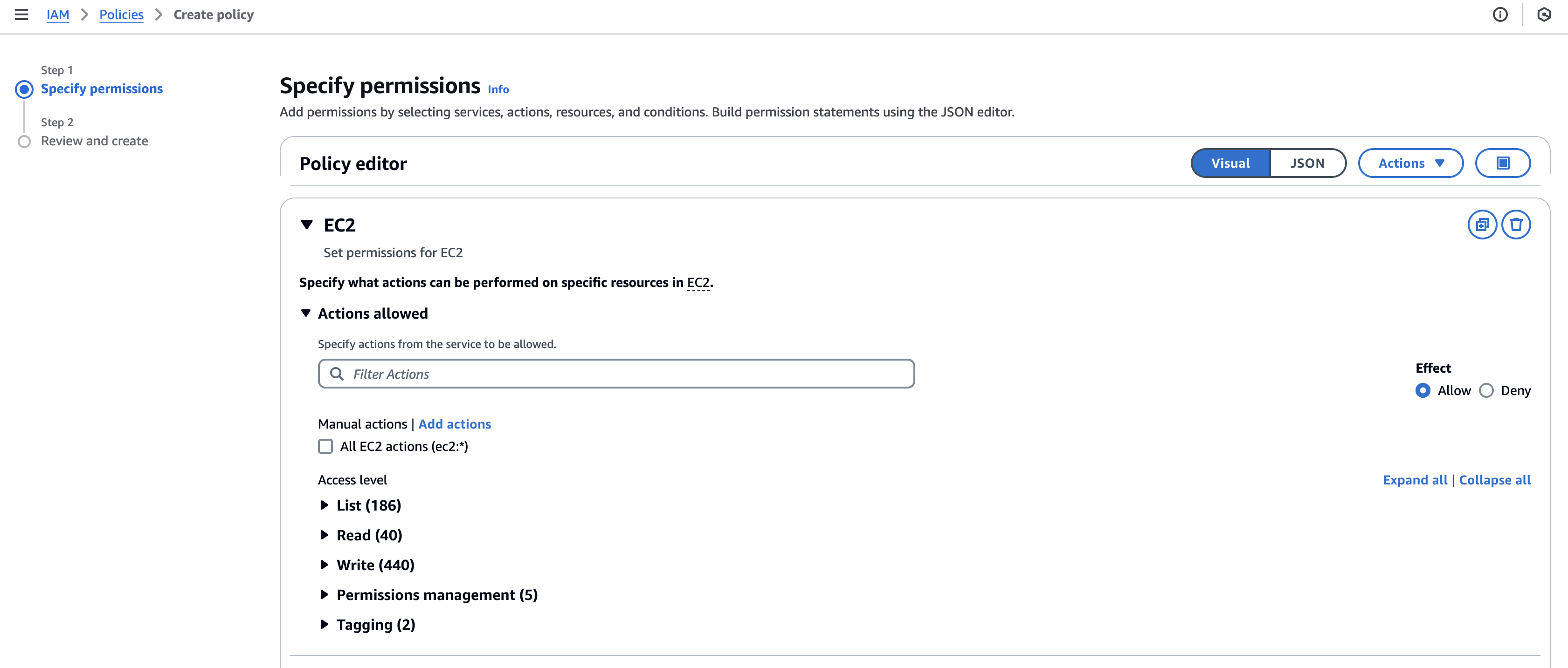
Figure: Filter Actions
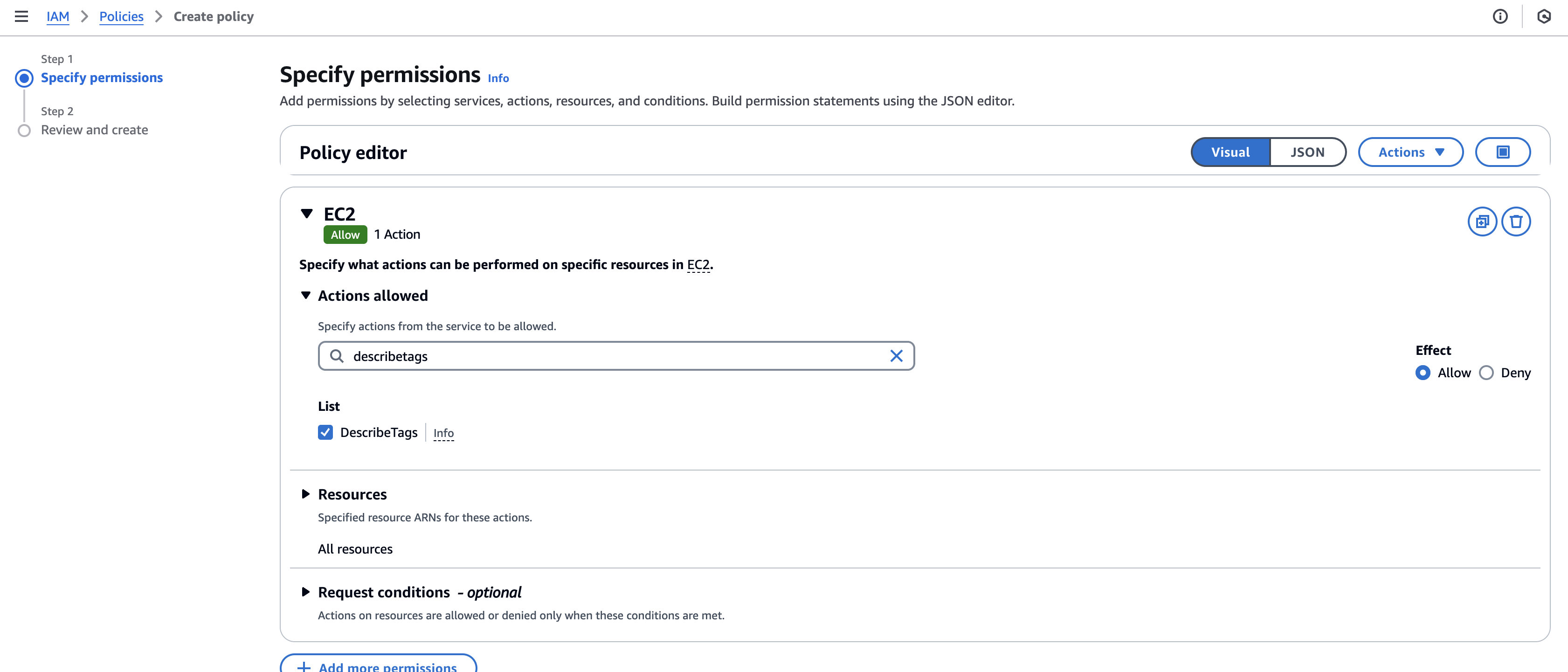
Figure: Filter Actions
- Alternatively, you can also add the tags using the JSON option.
{
    "Version": "2012-10-17",
    "Statement": [
        {
            "Sid": "VisualEditor0",
            "Effect": "Allow",
            "Action": [
                "ec2:DescribeInstances",
                "ec2:DescribeTags",
                "autoscaling:DescribeAutoScalingInstances"
            ],
            "Resource": "*"
        }
    ]
}
-
Click Next.
-
Enter a Policy name and an optional short description.
-
Click Create policy.
-
Confirm the policy was created.
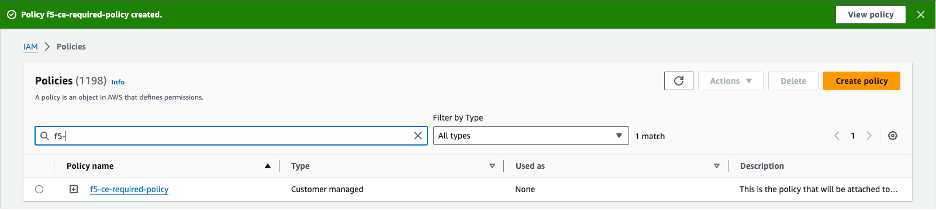
Figure: IAM Policy Confirmation
Step 3: Create and configure IAM role.
-
Under Access management, click Roles and then click Create role.
-
Confirm AWS service is selected.
-
From the Service or use case menu, select EC2. Then, click Next.
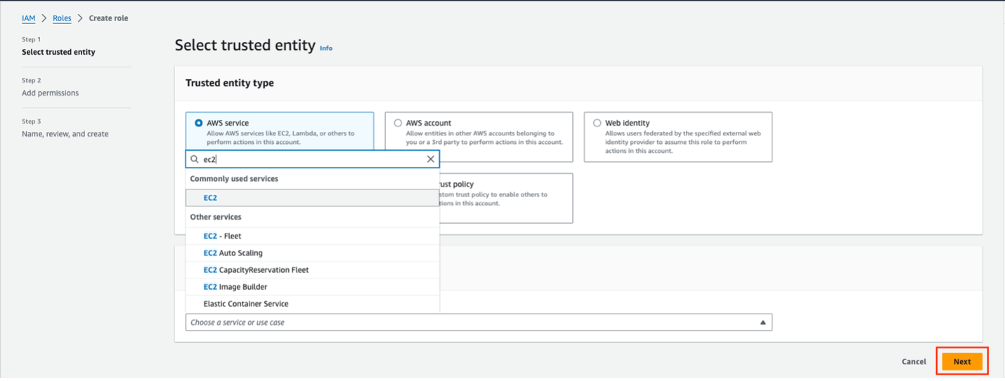
Figure: Create IAM Role
-
In the search box, find and select the policy previously created.
-
Click Next.
-
Enter a Role name and short description. Ensure that the role name and description clearly relate to the policy.
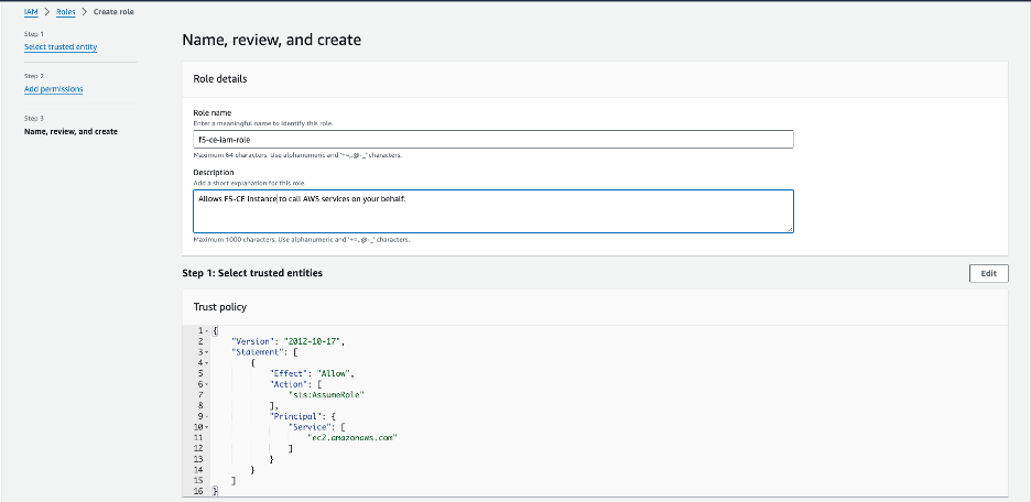
Figure: IAM Role Configuration
- Click Create role.
Create CE Security Group
You must create a security group and attach it to your EC2 instance.
-
In the EC2 service, select Network & Security > Security Groups.
-
Click Create security group.
-
Give the security group an indicative name.
-
For the inbound rules:
- Allowed SSH from the instance’s public IP address. This is where AWS figures out the public IP address that a user is configuring from and allows it. You can also use custom and put your corporate public address space.
- Allowed ICMP for troubleshooting.
- Allowed TCP Port 65500 for the local UI on the CE.
- For a three-node CE site, ensure that traffic is allowed among the nodes.
Important: Note that when you create load balancers to publish applications, you need to add additional rules in your security group to accept the traffic that comes to your virtual IP (VIP).
-
For the outbound rules:
- Add an allow-all rule.
-
After you finish, click Create security group.
-
Verify the security group was created with the correct inbound and outbound rules.
Create SSH Key Pair
You must create a key pair for SSH login into the EC2 instance (node) for troubleshooting purposes.
Step 1: Navigate to SSH key creation page.
-
In AWS Management Console, under Network & Security, click Key Pairs.
-
Click Create key pair.
Step 2: Configure SSH key pair.
-
Enter a key pair name.
-
Select the key pair type.
-
Select the key pair format.
-
After you finish, click Create key pair.
-
Afterwards, verify that the keys were created properly.
-
Download the key pair locally to your machine. You need the key pair to log into the EC2 instance (node).
Locate AMI ID and Hardware Image
Specific information is required to deploy a CE site. This information helps determine and locate the F5 Distributed Cloud Services certified hardware image and Amazon Machine Image (AMI) ID. Note that the AMI ID corresponds to a certified hardware image.
The following information is required to find the AMI ID:
- Site Type: Mesh
- Number of interfaces: Single or multi-NIC
- Region: AWS Region where you want to deploy your CE Site nodes
In addition to the AMI ID, you must look up the name of the certified hardware image.
As an example, if you are deploying a multi-NIC node in region us-west-1:
- Region: us-west-1
- Site Type: Mesh
- Interfaces: Dual
For the example above, the AMI ID of ami-0858c196c17ebf057 corresponds to the F5 Distributed Cloud Services hardware image of aws-byol-multi-nic-voltmesh.
-
To locate and download the AMI file, navigate to Cloud Images.
-
In the table, use the Region and AMI columns to search for your AMI file.
Create Site Token
Create a site token or use an existing token. If you are configuring a multi-node site, use the same token for all nodes. To create the token, see the Create Site Token section.
Modify EC2 User Data File
Download the raw .yml file to your machine and input the value of the site token into the Token field. See GitHub User Data File for more information. Afterwards, save the file on your machine as you need it for the user data when creating the EC2 instance VM (node).
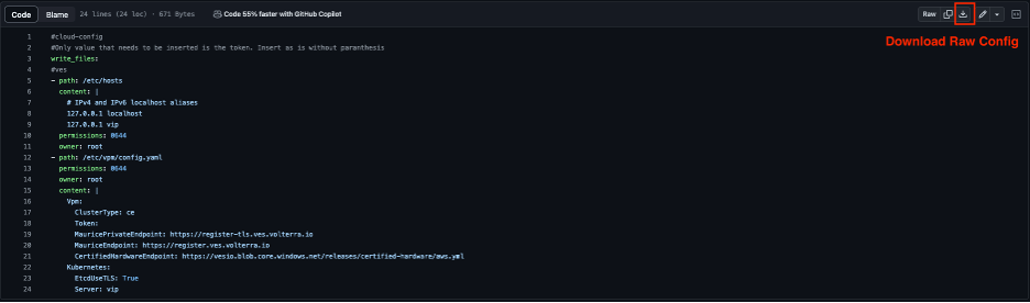
Figure: Raw YAML File
#cloud-config
#Only values that need to be inserted are the token and site name. Insert as is without parenthesis
write_files:
- path: /etc/hosts
  content: |
    # IPv4 and IPv6 localhost aliases
    127.0.0.1 localhost
    127.0.0.1 vip
  permissions: 0644
  owner: root
- path: /etc/vpm/config.yaml
  permissions: 0644
  owner: root
  content: |
    Vpm:
      ClusterType: ce
      ClusterName: #### TO BE REPLACED BY THE F5XC SECURE MESH SITE NAME ####
      Token: #### TO BE REPLACED BY F5XC API TOKEN ####
      MauricePrivateEndpoint: https://register-tls.ves.volterra.io
      MauriceEndpoint: https://register.ves.volterra.io
      CertifiedHardwareEndpoint: https://vesio.blob.core.windows.net/releases/certified-hardware/aws.yml
    Kubernetes:
      EtcdUseTLS: True
      Server: vip
      CloudProvider: disabled
Deploy Multi-Node Site
Follow these steps to create a three-node Secure Mesh Site.
For a multi-node site, the nodes are deployed in three separate Availability Zones (AZs). Examples include us-west-1a, us-west-1b, and us-west-1c. You need two subnets in each AZ (six subnets in total).
Note: The CE sites created in Distributed Cloud Console also use a workload subnet, but it is not a requirement and can be ignored for manually created sites.
Create Elastic IP Addresses
Create Elastic IP addresses to attach to the CE Site nodes.
Step 1: Navigate to Elastic IP address creation page.
-
Under Virtual private cloud, select Elastic IPs.
-
Click Allocate Elastic IP address.
Step 2: Configure Elastic IP addresses.
-
Click Add new tag.
-
Enter a key name and a name for the value (for example, f5-ce-eip-1).
-
Click Allocate.
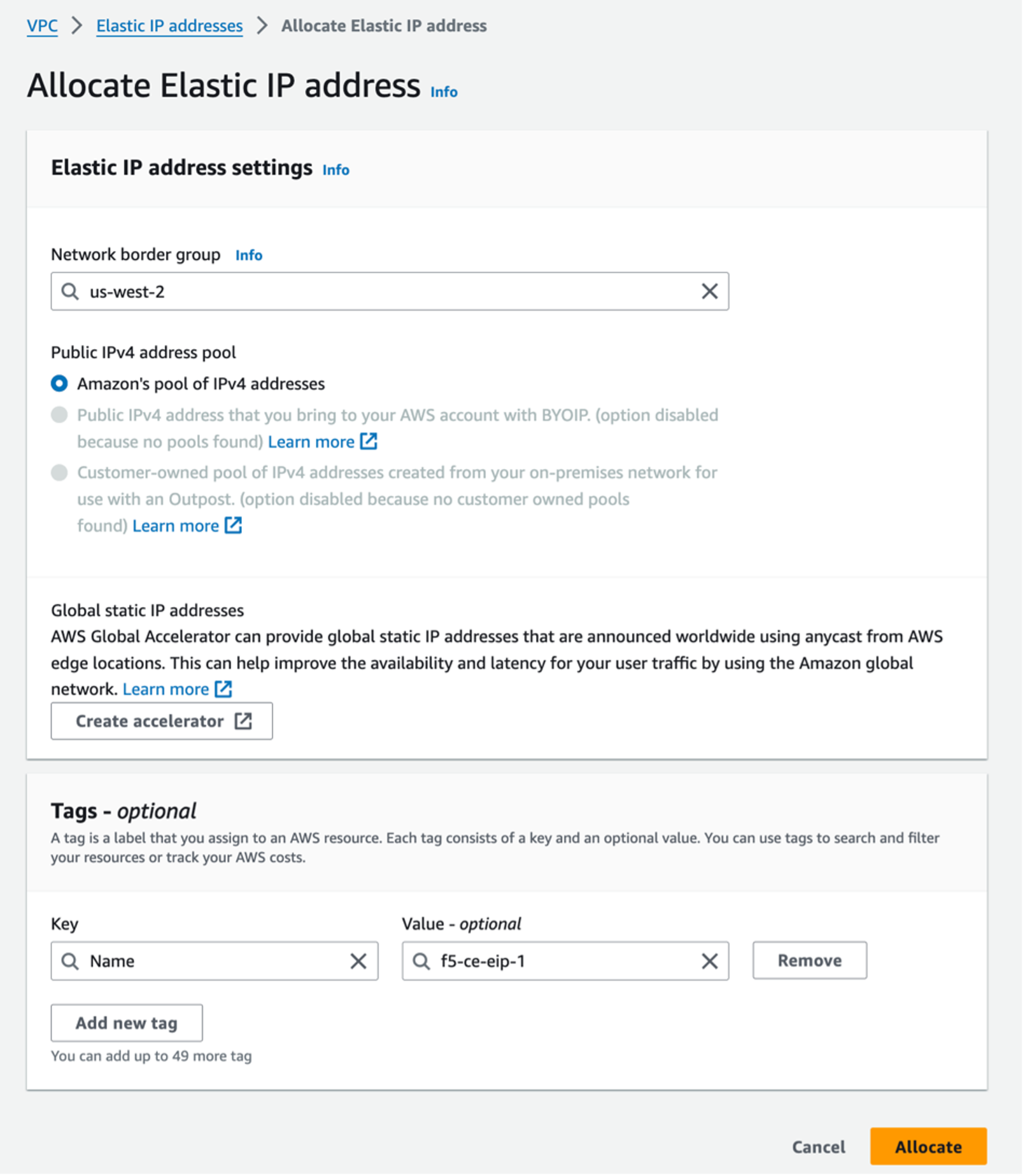
Figure: Allocate IP Addresses
- Repeat the above steps to create two more Elastic IP addresses (for example, f5-ce-eip-2 and f5-ce-eip-3) for node two and node three of your site. The elastic IP address above is used for node one of the Secure Mesh Site.
Create the CE Node Instances
Create the F5 CE EC2 instances (nodes) using the previously created parameters. F5 recommends that you create a table and fill it with the information before deploying the CE EC2 instances. See the table below for example parameters and explanations used for this guide.
The steps below show the nodes deployed in three Availability Zones (a, b, and c). However, your CE nodes can be deployed in any AZ as long as they are in separate AZs for redundancy.
| Parameter | Value | Notes |
|---|---|---|
| Name | f5-ce-node-1 f5-ce-node-2 f5-ce-node-3 | Names of EC2 instances (nodes). |
| Region | us-west-1 | Name of AWS region in which the CE Site nodes are deployed. |
| AMI ID | ami-0b91438f4f4bc1af9 | This is the AMI ID. |
| Certified hardware name | aws-byol-multi-nic-voltmesh | This is the certified hardware name. |
| Instance type | m5.2xlarge | Minimum instance requirements: 8 vCPUs, 32 GB RAM, 80 GB storage for Mesh nodes, and 100 GB storage for App Stack. Recommended instance types are m5.2xlarge and m5.4xlarge. |
| VPC name | f5-ce-vpc | Name of the AWS VPC in which the CE Site nodes are deployed. |
| VPC ID | vpc-03d062399d80cc2d1 | Existing VPC. |
| SLO subnets | SLO-subnet-public-a SLO-subnet-public-b SLO-subnet-public-c | Existing SLO subnet names across three AZs. |
| SLI subnets | SLI-subnet-private-a SLI-subnet-private-b SLI-subnet-private-c | Existing SLI subnet names across three AZs. |
| Key pair | f5-ce-keypair | Key pair created in AWS Management Console. |
| Security group | f5-ce-security-group | Name of security group created in AWS Management Console. |
| IAM instance profile | f5-ce-iam-role | Name of IAM profile created in AWS Management Console. |
| Elastic IP addresses | f5-ce-eip-1 f5-ce-eip-2 f5-ce-eip-3 | Names of elastic IP addresses created for nodes 1, 2, and 3. |
| Tag: site name | f5-ce | Optional tag. |
| Tag: ves-io-site-name | f5-ce-demo | Mandatory tag (equals site name). |
Tag without site name: kubernetes.io/cluster/<value-of-sitename> / tag with site name: kubernetes.io/cluster/f5-ce-demo | Owned. | Mandatory tag note that the value after /cluster/ is the site name. |
| Site name | f5-ce-demo | Equals ves-io-site-name value. |
| Token | Confidential. Value varies. | Value for site token ID generated in Distributed Cloud Console. |
| Storage | 80 GB for Mesh/100 GB for App Stack recommended. | Minimum disk space required. |
Step 1: Configure tags.
After you have set the site name, click Add additional tags to add the required tags.
Important: Without the tags labeled as mandatory, the site will not register.
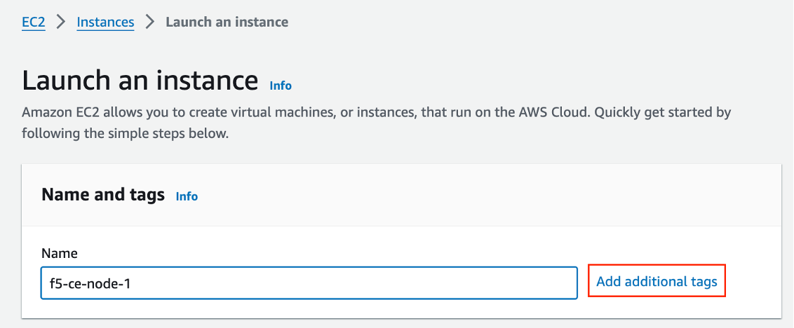
Figure: Add Tags
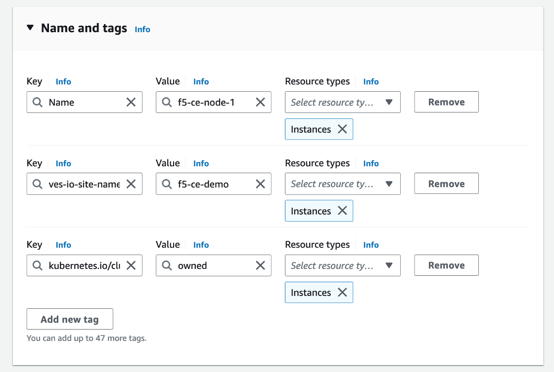
Figure: Add Tags
Step 2: Configure instance type.
-
Select the AMI per the parameters in the table above.
-
Select the instance type. Note that m5.2xlarge is the minimum instance type required to run the F5 CE software.
-
Select the key pair.
Step 3: Configure network interfaces.
-
Select the VPC and subnet (SLO-subnet-public-a), which are referenced in the parameters' table above. The subnet chosen is the subnet for Network interface 1 (SLO). Ensure that you are choosing the correct subnet so that the node one instance gets created in AZ a. Also, ensure that Auto-assign public IP is disabled as an Elastic IP address is used instead.
-
From the Common security groups menu, select the security group created previously (for example, f5-ce-security-group).
-
Under Advanced network configuration, for Network interface 1, enter a description for the interface as node1-slo.
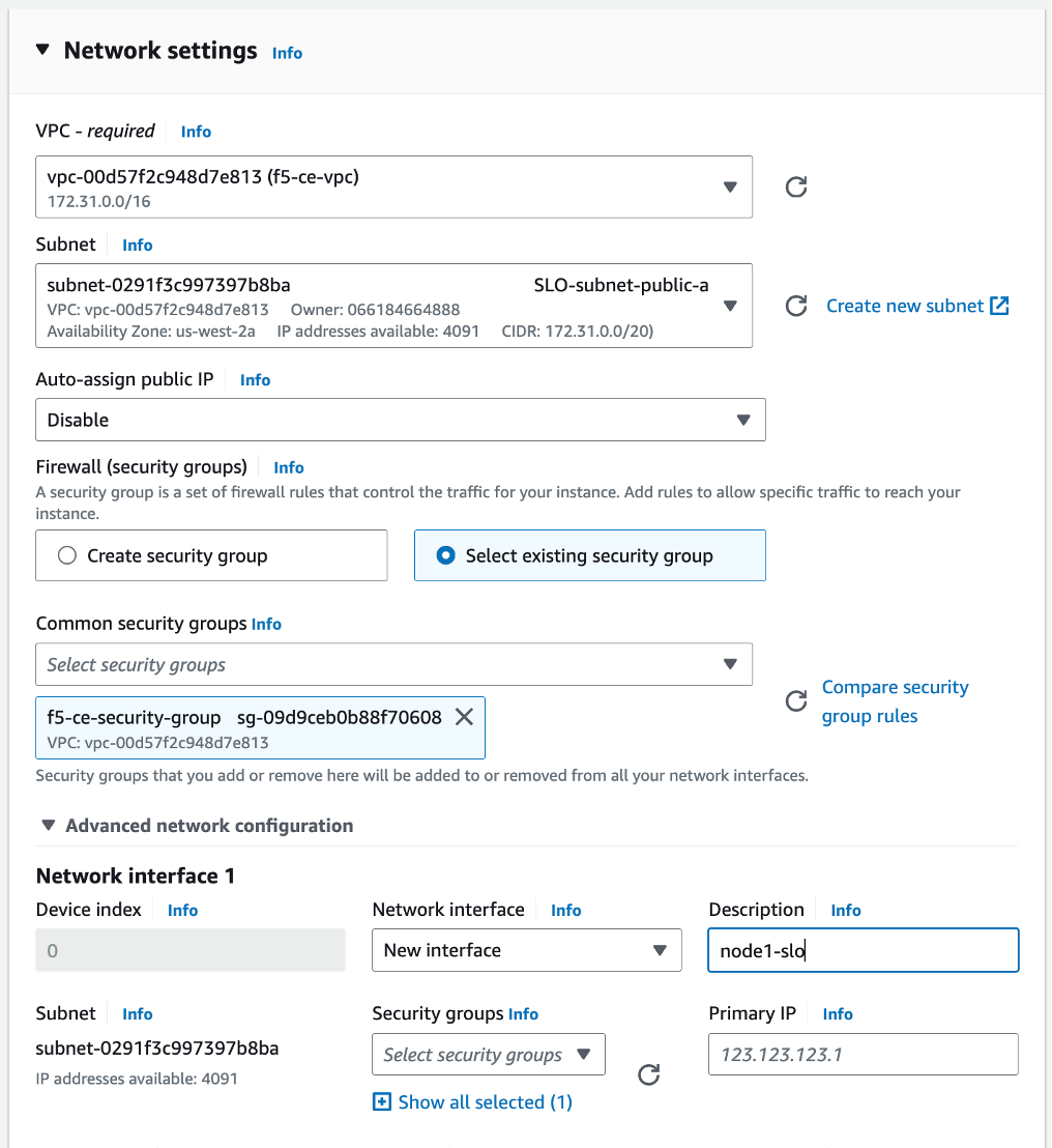
Figure: Configure Network Interface 1
-
Click Add network interface to create the SLI interface.
-
For Network interface 2 enter a description of node1-sli.
-
Select the subnet (SLI-subnet-private-a).
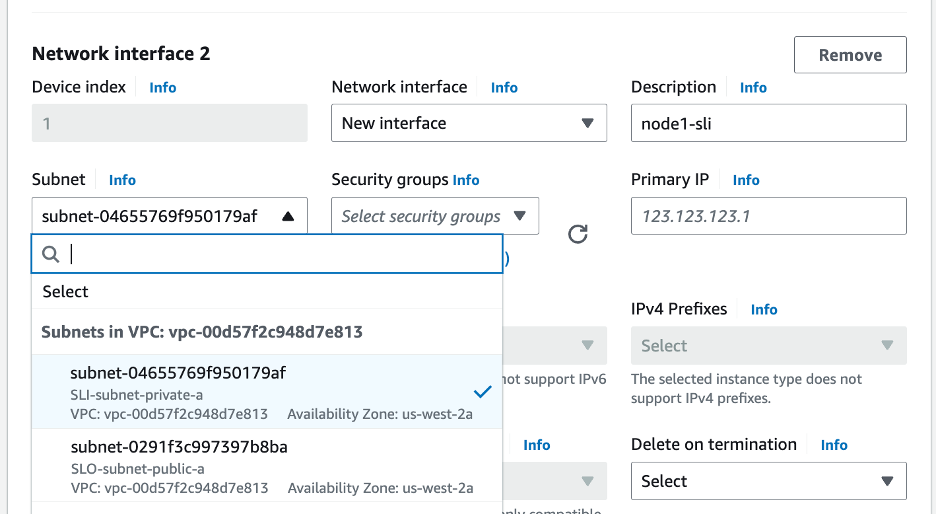
Figure: Configure Network Interface 2
Step 4: Configure network storage.
Configure the storage requirement (80 GB).
Step 5: Configure the advanced details.
-
Select the IAM instance profile (Role) per the parameters' table above.
-
Copy and paste the modified user data file into the User data - optional box.
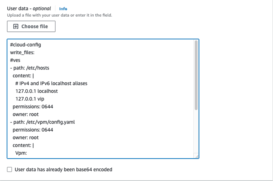
Figure: User Data Information
Step 6: Launch the instance.
Click Launch instance to create the EC2 instance.
Step 7: Create instances for node two and node three.
Repeat steps 1 to 6 to create instances for nodes two and three. Ensure that you are naming the instances (for example, f5-ce-node-2 and f5-ce-node-3) and their interfaces correctly, and using the correct subnets for the SLO and SLI interfaces to place the nodes in the correct AZs.
Associate Elastic IP Addresses to SLO Interfaces
After the EC2 instances are created, you must allocate the previously created Elastic IP addresses to the SLO interfaces on the corresponding nodes.
Step 1: Note down SLO interface ID.
Note down the SLO interface ID by navigating to the Networking tab under the f5-ce node one instance and getting the elastic network interface (ENI) ID of the SLO. Keep this information as you need it to assign the Elastic IP address to the interface.
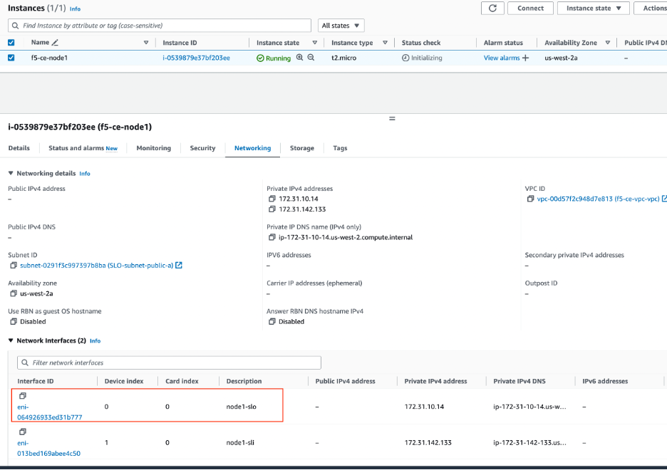
Figure: Associate IP Address to Interface
Step 2: Associate IP addresses to interface.
-
Select the Elastic IP address f5-ce-eip-1 and then navigate to Actions > Associate Elastic IP address.
-
Select Resource type as Network interface.
-
Enter the ENI ID.
-
Click Associate.
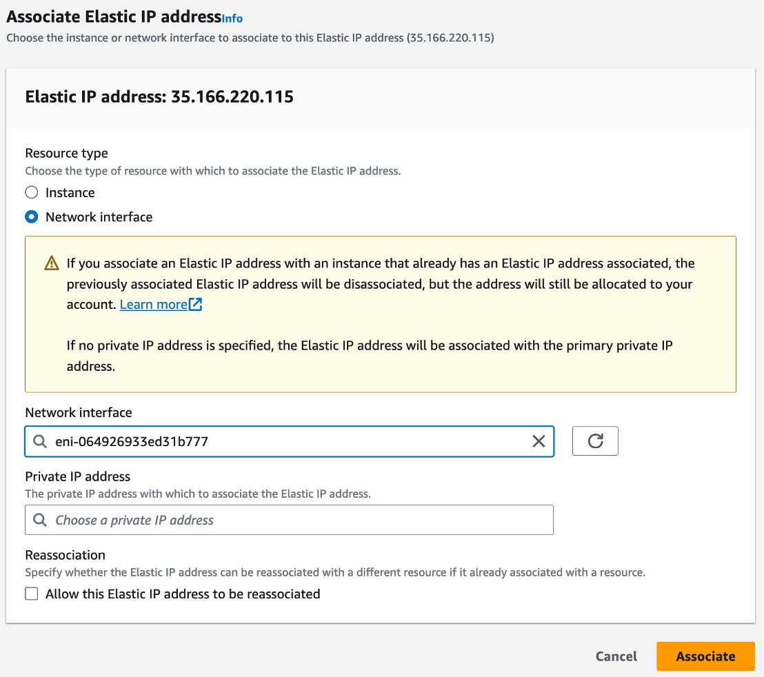
Figure: Associate IP Address to Interface
Step 3: Repeat steps for other nodes.
Repeat the steps above to associate the two other Elastic IP addresses (for example, f5-ce-eip-2 and f5-ce-eip-3) to the SLO interface on node two and node three, respectively.
Stop Source/Destination Checks
In AWS, the source/destination check is a feature that ensures that an EC2 instance is only responsible for traffic that it sends or receives. By default, this check is enabled for all EC2 instances, meaning that each instance is expected to handle only the network traffic that originates from or is destined to its own IP address.
In the case of an F5 CE Site, the instance is a Network Virtual Appliance (NVA) that outgoing and incoming traffic needs to transit through. Therefore, you need to disable the source/destination check on the F5 CE EC2 instances.
- For your EC2 instances, navigate to Actions > Networking > Change source/destination check.
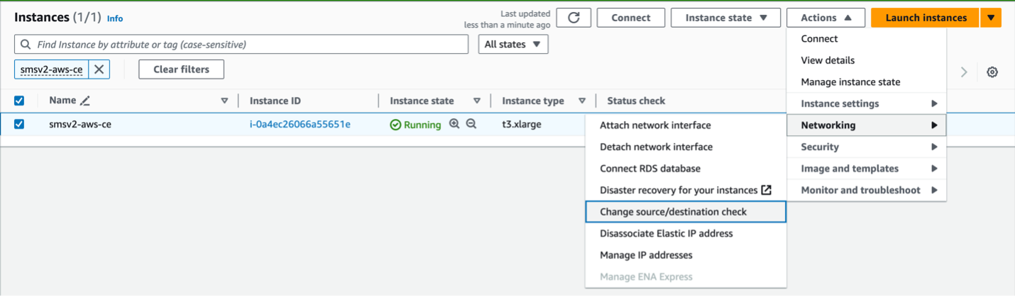
Figure: Networking
- Check the box for Stop.
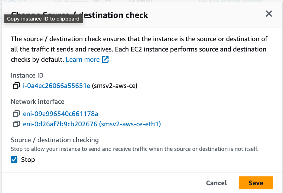
Figure: Stop Checkbox
- Click Save.
Deploy Single-Node Site
Follow these steps to create a single-node Secure Mesh Site.
In this example, a dual interface single-node CE site is being deployed. Since the site has two interfaces, two subnets are required for each node. One for SLI and the other for SLO. For a single-node site, the node instance is deployed in only one Availability Zone (AZ), and both subnets are in the same AZ (for example, us-west-1a).
Note: The CE sites created in Distributed Cloud Console also use a workload subnet, but it is not a requirement and can be ignored for manually created sites.
Create Elastic IP Address
Create an Elastic IP address to attach to the CE site node.
Step 1: Navigate to Elastic IP address creation page.
-
Under Virtual private cloud, select Elastic IPs.
-
Click Allocate Elastic IP address.
Step 2: Configure Elastic IP address.
-
Click Add new tag.
-
Enter a key name and a name for the value (for example, f5-ce-eip).
-
Click Allocate.
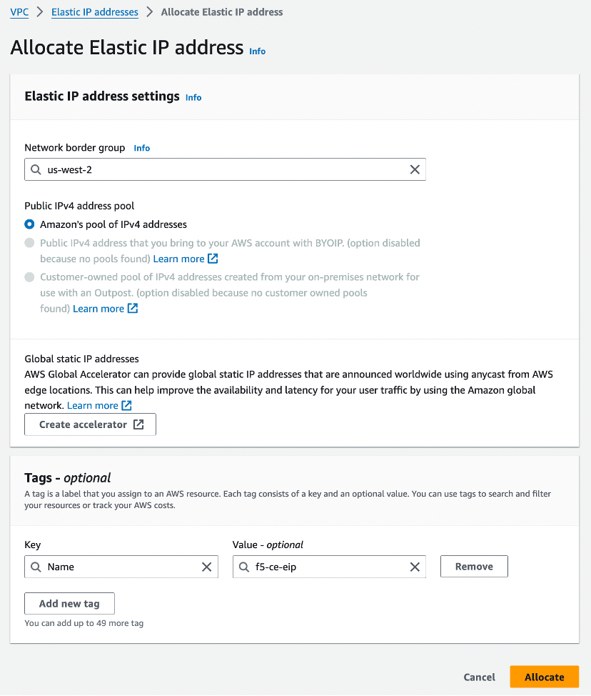
Figure: Allocate Elastic IP Address
Create the CE Node Instance
Create the F5 CE EC2 instance (node) using the previously created parameters. F5 recommends that you create a table and fill it with the information before deploying the CE EC2 instance (node). See the table below for example parameters and explanations used for this guide.
| Parameter | Value | Notes |
|---|---|---|
| Name | f5-ce | Name of EC2 instance (node). |
| Region | us-west-1 | Name of AWS region in which the CE Site node is deployed. |
| AMI ID | ami-0b91438f4f4bc1af9 | This is the AMI ID. |
| Certified hardware name | aws-byol-multi-nic-voltmesh | This is the certified hardware name. |
| Instance type | m5.2xlarge | Minimum instance requirements: 8 vCPUs, 32 GB RAM, 80 GB storage for Mesh nodes, and 100 GB storage for App Stack. Recommended instance types are m5.2xlarge and m5.4xlarge. |
| VPC name | f5-ce-vpc | Name of the AWS VPC in which the CE Site node is deployed. |
| VPC ID | vpc-03d062399d80cc2d1 | Existing VPC. |
| SLO subnet | SLO-subnet-public | Existing SLO subnet name. |
| SLI subnet | SLI-subnet-private | Existing SLI subnet name. |
| Key pair | f5-ce-keypair | Key pair created in AWS Management Console. |
| Security group | f5-ce-security-group | Name of security group created in AWS Management Console. |
| IAM Instance Profile | f5-ce-iam-role | Name of IAM profile created in AWS Management Console. |
| Elastic IP address | f5-ce-eip | Name of elastic IP address created for node. |
| Tag: site name | f5-ce | Optional tag. |
| Tag: ves-io-site-name | f5-ce-demo | Mandatory tag (equals site name). |
Tag without site name: kubernetes.io/cluster/<value-of-sitename> / tag with site name: kubernetes.io/cluster/f5-ce-demo | Owned. | Mandatory tag note that the value after /cluster/ is the site name. |
| Site name | f5-ce-demo | Equals ves-io-site-name value. |
| Token | Confidential. Value varies. | Value for site token ID generated in Distributed Cloud Console. |
| Storage | 80 GB for Mesh/100 GB for App Stack recommended. | Minimum disk space required. |
Step 1: Configure tags.
After you have set the site name, click Add additional tags to add the required tags.
Important: Without the tags labeled as mandatory, the site will not register.
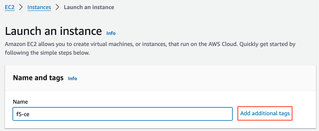
Figure: Add Tags
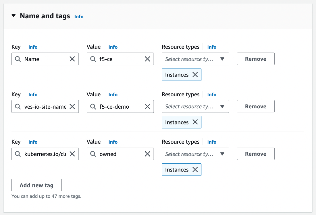
Figure: Add Tags
Step 2: Configure instance type.
-
Select the AMI per the parameters in the table above.
-
Select the instance type. Note that m5.2xlarge is the minimum instance type required to run the F5 CE software.
-
Select the key pair.
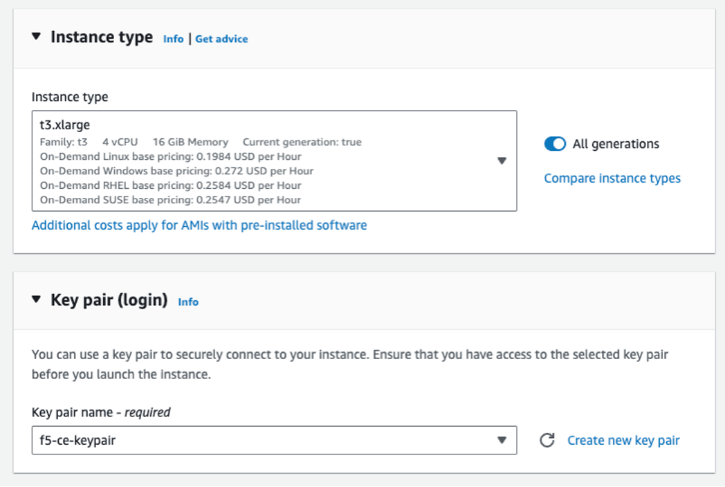
Figure: Add Key Pairs
Step 3: Configure network interfaces.
-
Select the VPC and subnet (SLO-subnet-public), which are referenced in the parameters' table above. Ensure that Auto-assign public IP is disabled as an Elastic IP address is used instead.
-
From the Common security groups menu, select the security group (for example, f5-ce-security-group) created previously.
-
Under Advanced network configuration, for Network interface 1 enter a description for the interface as slo.
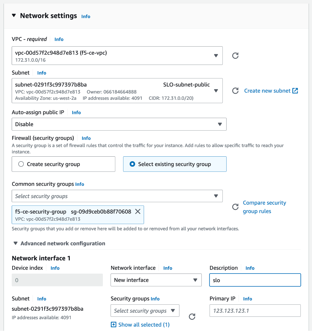
Figure: Configure Network Interface 1
-
Click Add network interface to create the SLI interface.
-
For Network interface 2 enter a description of sli.
-
Select the subnet (for example, SLI-subnet-private).
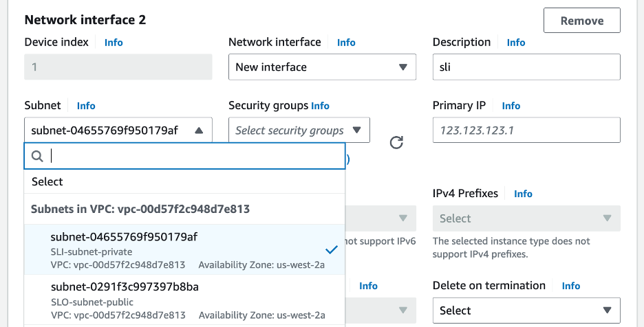
Figure: Configure Network Interface 2
Step 4: Configure network storage.
Configure the storage requirement (80 GB).
Step 5: Configure the advanced details.
-
Select the IAM instance profile (Role) per the parameters' table above.
-
Copy and paste the modified user data file into the User data - optional box.
Figure: User Data Information
Step 6: Launch the instance.
Click Launch instance to create the EC2 instance.
Associate Elastic IP Address to SLO Interface
After the EC2 instance is created, you need to allocate the previously created Elastic IP address to the SLO interface on the CE node.
Step 1: Note down SLO interface ID.
Note down the SLO interface ID by navigating to the Networking tab under the instance (for example, f5-ce) and getting the elastic network interface (ENI) ID of the SLO. Keep this information as you need it to assign the Elastic IP address to the interface.
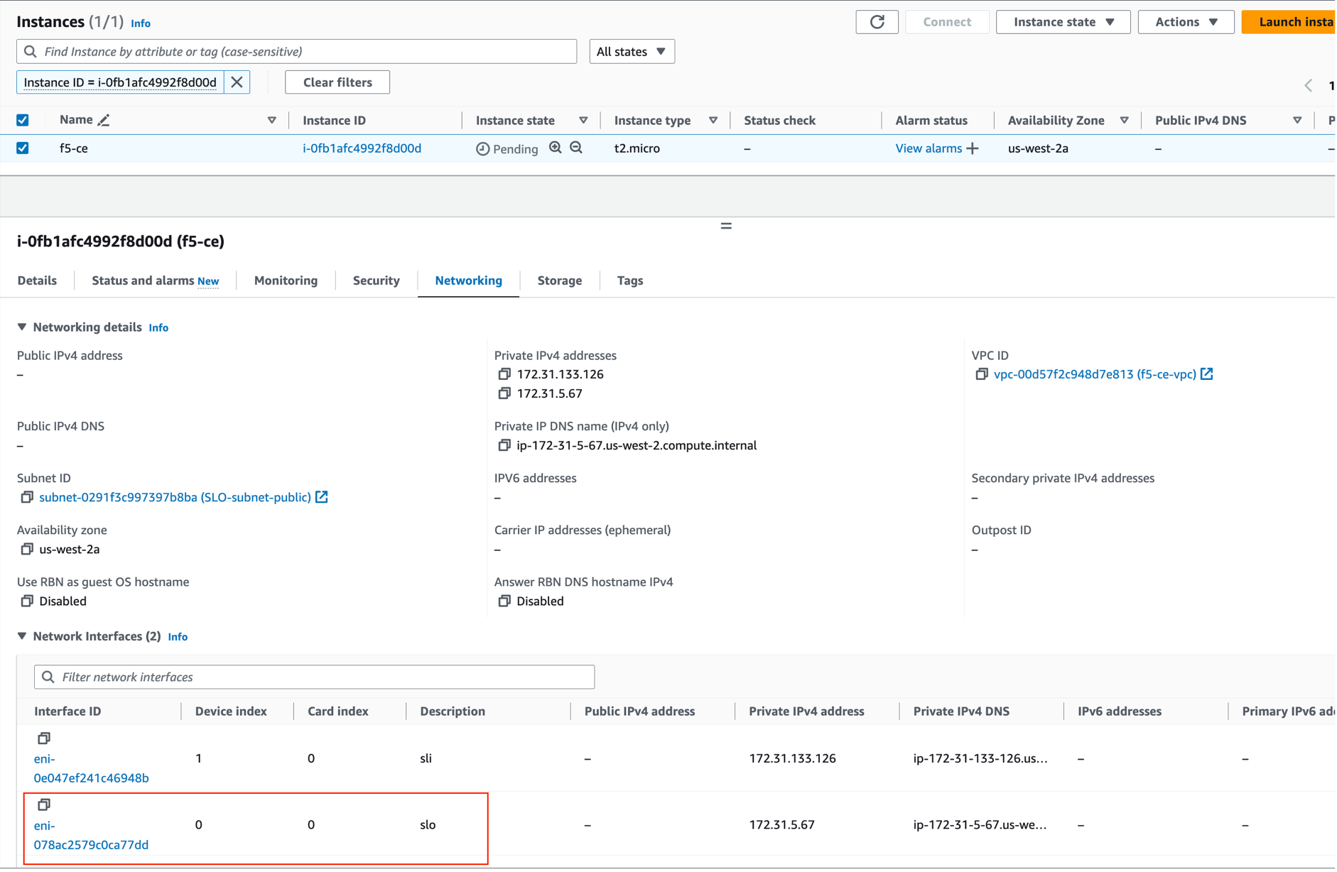
Figure: Associate IP Address to Interface
Step 2: Associate IP address to interface.
-
Select the Elastic IP address (for example, f5-ce-eip) and then navigate to Actions > Associate Elastic IP address.
-
Select Resource type as Network interface.
-
Enter the ENI ID.
-
Click Associate.
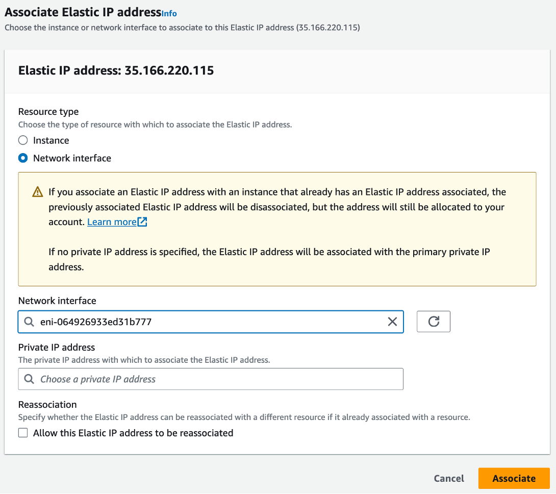
Figure: Associate IP Address to Interface
Stop Source/Destination Checks
In AWS, the source/destination check is a feature that ensures that an EC2 instance is only responsible for traffic that it sends or receives. By default, this check is enabled for all EC2 instances, meaning that each instance is expected to handle only the network traffic that originates from or is destined to its own IP address.
In the case of an F5 CE Site, the instance is a Network Virtual Appliance (NVA) that outgoing and incoming traffic needs to transit through. Therefore, you need to disable the source/destination check on the F5 CE EC2 instance.
- For your EC2 instance, navigate to Actions > Networking > Change source/destination check.
Figure: Networking
- Check the box for Stop.
Figure: Stop Checkbox
- Click Save.
Create and Register Secure Mesh Site
Follow the Create Secure Mesh Site guide to create a Secure Mesh Site object and register the nodes to the site.
Considerations for CE Sites Behind NAT Gateway
In a regular deployment, each CE node has an Elastic IP address associated with the Site Local Outside (SLO) interface, and the SLO route table routes the outgoing traffic via the Internet Gateway using the Elastic IP address as the NAT IP address.
But, for scenarios where there is a requirement to have the CE site deployed without a public IP address, you can place the CE site behind a NAT Gateway. This can be the AWS NAT gateway or any third-party instance, like a firewall used as a NAT gateway.
If you are deploying a site in this scenario, there are a few differences to note:
-
There is no public IP association with the CE(s).
-
You must ensure the CE can reach the Internet through its SLO interface.
-
From the AWS side, ensure that the routing table from the SLO subnet has a default route of 0.0.0.0/0 that points to the NAT Gateway.
-
The NAT Gateway is a zonal object. In other words, it belongs to one Availability Zone (AZ). Therefore, in the case of a three-node CE cluster, you might want to deploy additional NAT Gateways for high availability.
Single Node Single Interface Site Differences (Mesh and App Stack)
Both App Stack and single NIC Mesh CE sites have a single interface and are therefore similar when deployed. It is the same procedure for single node single NIC Mesh and App Stack CE sites.
The three differences for single NIC site include the following:
- AMI
- Certified hardware image name
- Only have an SLO instead of both SLO/SLI, which means there is no need to add a second network interface. This also means that a single subnet (SLO) is required.
- Elastic IP assignment becomes easier, as you can directly assign the address to the instance instead of figuring out which interface is the SLO for dual-NIC scenarios.
- For App Stack CE sites, you need to add the site via Site Management > App Stack Sites instead of Secure Mesh Sites.
- For App Stack CE sites, F5 recommends the storage amount as 100 GB.
Three-Node Cluster Site Differences
It is the same procedure for three-node multi-NIC Mesh sites and three-node App Stack sites.
The differences include the following:
- When creating the instance, leverage the Number of instances option from AWS to automatically create three EC2 instances. This avoids the hassle of repeating the process for each instance and ensures uniform configuration.
- Ensure that each EC2 instance has a unique name as it makes for smoother operations.
- Ensure that the CE Security Group allows communication between the nodes (intra-cluster communication). As an example, this guides provides steps to update the CE security group to allow traffic from itself. This can also be achieved with an IP-based rule.
- Ensure the same tagging structure.
- Three pending registration requests appear. As is the case for single-node, you do not accept the request until you first create the Site Mesh Group object.
- The Secure Mesh Site object has the same configuration as a single-node, with the only difference being three nodes (master-0, master-1 and master-2). Note that the names can be chosen. For App Stack sites, add the site via Site Management > App Stack Sites instead of Secure Mesh Sites. Everything else remains the same.
- You must approve the three pending registration requests one by one, where all will have the same Cluster Name (Site Name). You must update the cluster size to 3. This step must be repeated on every registration request.
- For the tags, ensure that all three EC2 instances share the same tags. Note that the Name does not provide any value for registration. This is the same procedure for single node sites.
Troubleshooting
For troubleshooting and opening a support case, see the Troubleshooting Manual Site Deployment Registration Issues guide. It provides step-by-step instructions to debug and resolve the issues that may arise due to Distributed Cloud published Terraform errors, networking and security misconfiguration, or CE internal process issues. The guide also provides instructions for contacting the F5 Distributed Cloud Support Team if you are unable to resolve the issue.
Concepts
References
- AWS VPC Policies and Permissions Reference
- Create AWS Site (Orchestrated)
- Deploy Site in AWS (Terraform)
On this page:
- Objective
- Site Types and Scenarios
- Prerequisites
- Procedure
- Create IAM Policy and Role
- Create CE Security Group
- Create SSH Key Pair
- Locate AMI ID and Hardware Image
- Create Site Token
- Modify EC2 User Data File
- Deploy Multi-Node Site
- Create Elastic IP Addresses
- Create the CE Node Instances
- Associate Elastic IP Addresses to SLO Interfaces
- Stop Source/Destination Checks
- Deploy Single-Node Site
- Create Elastic IP Address
- Create the CE Node Instance
- Associate Elastic IP Address to SLO Interface
- Stop Source/Destination Checks
- Create and Register Secure Mesh Site
- Considerations for CE Sites Behind NAT Gateway
- Single Node Single Interface Site Differences (Mesh and App Stack)
- Three-Node Cluster Site Differences
- Troubleshooting
- Concepts
- References